Quick & Easy Steps to Use Arduino IDE for ESP32 Development
Contents
Introduction
The ESP32 is a powerful microcontroller with built-in Wi-Fi and Bluetooth capabilities, making it popular for Internet of Things (IoT) applications. It offers excellent performance at an affordable price, attracting developers worldwide.

The Arduino IDE provides a user-friendly platform that simplifies writing, compiling, and uploading code to the ESP32. Its ease of use makes it a great choice for both beginners and experienced developers.

In this blog, I will guide you from scratch on how to use the Arduino IDE to develop ESP32 applications and demonstrate how to control an LED on the ESP32 with a simple program.
Installing the Arduino IDE to Develop ESP32
If you haven't installed the Arduino IDE yet, head over to the official Arduino website to download and install the latest version. The Arduino IDE is a cross-platform tool, compatible with Windows, macOS, and Linux.
Configuring Arduino IDE to Support ESP32
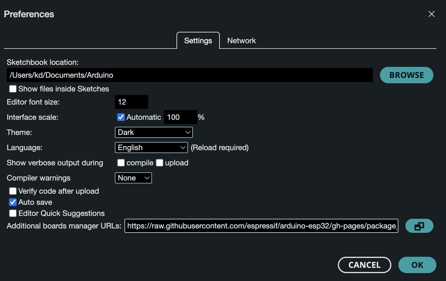
1. Open the Arduino IDE and select Arduino > Preferences (for macOS).

2. In the Additional Boards Manager URLs field, add the following URL:

https://raw.githubusercontent.com/espressif/arduino-esp32/gh-pages/package_esp32_index.json

* If you already have other URLs in the field, you can add this URL after them, separated by commas.

3. Click OK to save the settings.
Installing ESP32 Board Support
1. Open the Arduino IDE and go to Tools > Board > Board Manager.
2. In the search box, type ESP32, find "esp32" by Espressif Systems, and click Install.
Selecting the ESP32 Development Board
After installation, go to Tools > Board and select ESP32 Dev Module from the list. This is a commonly used ESP32 board model.
Using printf() to Control the ESP32’s LED Blinking
We'll use the built-in LED, typically connected to GPIO 2. In this example, we'll turn the LED on and off every second and use printf() to display status updates in the serial monitor.
// Define the pin number for the built-in LED
#define LED_BUILTIN 2

void setup() {
  // Initialize serial communication at 115200 baud rate for debugging
  Serial.begin(115200);

  // Initialize the LED pin as an output
  pinMode(LED_BUILTIN, OUTPUT);

  // Print a setup completion message
  printf("Setup complete. LED is ready to blink.\n");
}

void loop() {
  // Turn the LED on
  digitalWrite(LED_BUILTIN, HIGH);
  printf("LED is ON\n");
  delay(1000);  // Wait for 1 second

  // Turn the LED off
  digitalWrite(LED_BUILTIN, LOW);
  printf("LED is OFF\n");
  delay(1000);  // Wait for 1 second
}

// Custom printf function to format and send output to the serial monitor
int printf(const char* format, ...) {
  char buffer[128];   // Create a buffer to store formatted output
  va_list args;       // Variable argument list

  va_start(args, format);            // Initialize args to store all values after 'format'
  vsnprintf(buffer, sizeof(buffer), format, args);  // Create formatted string in buffer
  va_end(args);                      // Clean up the variable argument list

  return Serial.print(buffer);       // Output the buffer to the serial monitor
}
* pinMode(LED_BUILTIN, OUTPUT) sets the built-in LED (connected to GPIO2) as an output pin.
* In the setup() function, we initialize serial communication with Serial.begin(115200) and print a message to indicate setup completion.
* In the loop() function, digitalWrite() is used to turn the LED on and off, while the custom printf() function prints status messages ("LED is ON" and "LED is OFF").
* The custom printf() function formats the message using vsnprintf() and sends it to the serial monitor via Serial.print().
Uploading the Program to ESP32
1. Connect the ESP32 development board to your computer using a USB data cable.

2. In the Arduino IDE, go to Tools > Port and select the correct port (for example, it is usually COM3 on Windows and /dev/ttyUSB0 on Linux/macOS).

3. Click the Upload button to upload the program to the ESP32.
Results
After uploading the program, open the Arduino IDE's Serial Monitor (shortcut: Ctrl + Shift + M or Command + Shift + M on macOS) and set the baud rate to 115200 to match Serial.begin().

You should see the following output in the serial monitor:
Setup complete. LED is ready to blink.
LED is ON
LED is OFF
LED is ON
LED is OFF
...
Conclusion
We've shown how to set up the Arduino IDE to support ESP32 and wrote a simple program to control the built-in LED using printf() for debugging. This project is an excellent starting point for exploring the ESP32's capabilities in IoT applications. As you continue learning, you can expand it by integrating Wi-Fi, Bluetooth, sensors, and other peripherals for more advanced projects.

The key takeaway is that the ESP32 combined with the Arduino IDE makes microcontroller development and debugging simpler. The printf() function helps track your program's execution, identify errors, and optimize your code.

Get started and have fun experimenting with the ESP32!
