Learn C++ with ESP32 : LED Control
Introduction
In embedded systems development, ESP32 is a popular development board known for its powerful processing and wireless communication features. In this article, we will use C++'s object-oriented features to create a class that controls an LED, learning how to develop on ESP32 in the process. We will implement the project using ESP-IDF (Espressif IoT Development Framework) and Visual Studio Code.
內容
Setting up the Development Environment
1. Install Visual Studio Code: Download and install it from the official VS Code website.
2. Install the ESP-IDF Plugin: You can install the ESP-IDF extension for VS Code by searching for it in the Extensions tab.
Creating a New Project
1. Open Visual Studio Code, press Ctrl (Cmd) + Shift + P, and type ESP-IDF: New Project.

2. Select a template project (like the blink example), name your project (e.g., LED_Control), and choose the location to store it.

3. The system will automatically generate a new ESP-IDF project with basic CMake files and example code.
Project Structure
my_project/
├── CMakeLists.txt
├── main/
│   ├── CMakeLists.txt
│   └── main.cpp
└── ...
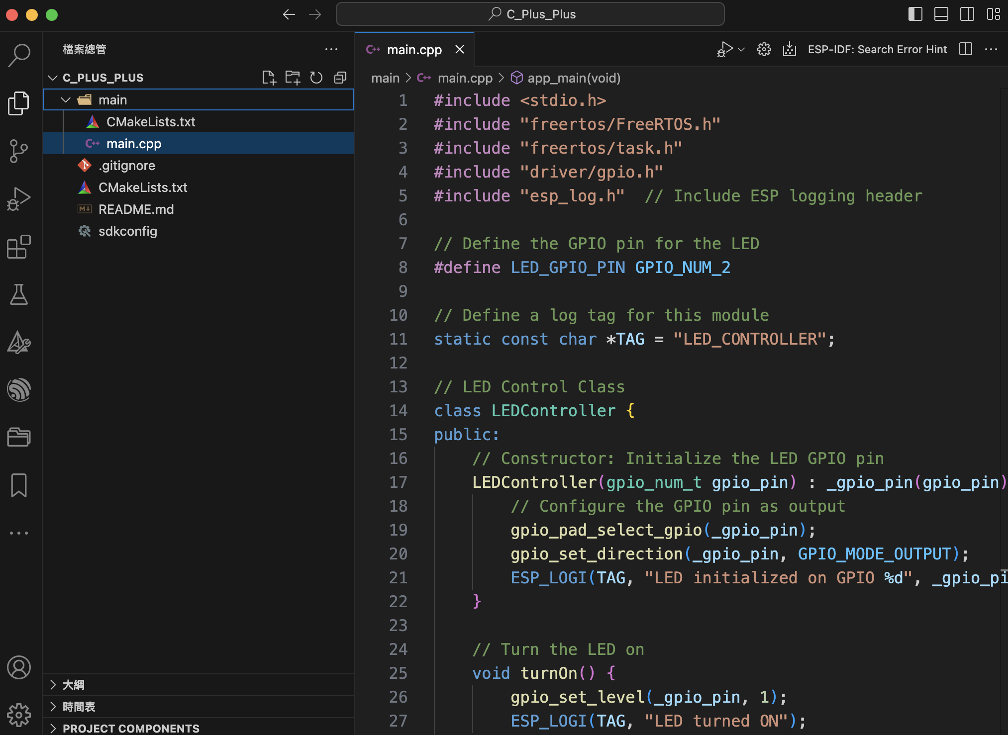
Using a C++ Class to Control the LED
Open the main/main.cpp file and modify it to include the following code:
#include <stdio.h>
#include "freertos/FreeRTOS.h"
#include "freertos/task.h"
#include "driver/gpio.h"
#include "esp_log.h"  // Include ESP logging header

// Define the GPIO pin for the LED
#define LED_GPIO_PIN GPIO_NUM_2

// Define a log tag for this module
static const char *TAG = "LED_CONTROLLER";

// LED Control Class
class LEDController {
public:
    // Constructor: Initialize the LED GPIO pin
    LEDController(gpio_num_t gpio_pin) : _gpio_pin(gpio_pin) {
        // Configure the GPIO pin as output
        gpio_pad_select_gpio(_gpio_pin);
        gpio_set_direction(_gpio_pin, GPIO_MODE_OUTPUT);
        ESP_LOGI(TAG, "LED initialized on GPIO %d", _gpio_pin);
    }

    // Turn the LED on
    void turnOn() {
        gpio_set_level(_gpio_pin, 1);
        ESP_LOGI(TAG, "LED turned ON");
    }

    // Turn the LED off
    void turnOff() {
        gpio_set_level(_gpio_pin, 0);
        ESP_LOGI(TAG, "LED turned OFF");
    }

    // Make the LED blink with a specified interval (in milliseconds)
    void blink(int interval_ms) {
        turnOn();  // Turn the LED on
        ESP_LOGI(TAG, "LED is blinking ON");
        vTaskDelay(interval_ms / portTICK_PERIOD_MS);  // Delay for the specified interval
        turnOff();  // Turn the LED off
        ESP_LOGI(TAG, "LED is blinking OFF");
        vTaskDelay(interval_ms / portTICK_PERIOD_MS);  // Delay again
    }

private:
    gpio_num_t _gpio_pin;  // Store the GPIO pin number for the LED
};

// Main program
extern "C" void app_main(void) {
    // Create an LED controller object for GPIO 2
    LEDController led(LED_GPIO_PIN);

    // Turn the LED on for 2 seconds
    ESP_LOGI(TAG, "Turning LED on for 2 seconds...");
    led.turnOn();  // Turn on the LED
    vTaskDelay(2000 / portTICK_PERIOD_MS);  // Wait for 2 seconds

    // Turn the LED off for 2 seconds
    ESP_LOGI(TAG, "Turning LED off for 2 seconds...");
    led.turnOff();  // Turn off the LED
    vTaskDelay(2000 / portTICK_PERIOD_MS);  // Wait for 2 seconds

    // Blink the LED 5 times with a 500ms interval
    ESP_LOGI(TAG, "Blinking LED 5 times with 500ms interval...");
    for (int i = 0; i < 5; ++i) {
        led.blink(500);  // Blink every 500 milliseconds
    }

    // Turn the LED on again for 3 seconds
    ESP_LOGI(TAG, "Turning LED on again for 3 seconds...");
    led.turnOn();  // Turn on the LED
    vTaskDelay(3000 / portTICK_PERIOD_MS);  // Keep it on for 3 seconds

    // Finally, turn the LED off
    ESP_LOGI(TAG, "Turning LED off finally...");
    led.turnOff();  // Turn off the LED
}
Code Explanation
LEDController Class:
Provides three main methods:
1. turnOn(): Turns on the LED.
2. turnOff(): Turns off the LED.
3. blink(): Makes the LED blink once, with the interval specified as a parameter.
app_main() Function:
In the app_main() function, we perform the following actions:
1. Turn the LED on for 2 seconds.
2. Turn the LED off for 2 seconds.
3. Blink the LED 5 times, with a 500ms interval.
4. Turn the LED on for 3 more seconds.
5. Finally, turn the LED off.
Building and Flashing the Project
Use the "ESP32-IDF: Build, Flash and Monitor" icon located at the bottom of the VS Code window to build and flash the code onto your ESP32 board.
Program Output
After running the program, you will see output in the terminal like this:
I (0) LED_CONTROLLER: Turning LED on for 2 seconds...
I (2000) LED_CONTROLLER: Turning LED off for 2 seconds...
I (4000) LED_CONTROLLER: Blinking LED 5 times with 500ms interval...
I (4500) LED_CONTROLLER: LED is blinking ON
I (5000) LED_CONTROLLER: LED is blinking OFF
...
I (7000) LED_CONTROLLER: Turning LED on again for 3 seconds...
I (10000) LED_CONTROLLER: Turning LED off finally...
Conclusion
In this blog, we demonstrated how to use the ESP-IDF's logging system (esp_log) to manage log outputs and control an LED on the ESP32, while also logging relevant operational messages. With the use of ESP_LOGI(), we can conveniently track the status of the program, which is very useful for debugging and performance monitoring.

By utilizing the logging system, you can flexibly set different log levels to monitor the details of the program's execution at various stages. Hopefully, this helps you better understand the logging feature in ESP32 development!
