Mastering ESP32 UART | Complete Guide for Sending and Receiving Data
This comprehensive guide explores the fundamentals of ESP32 UART (Universal Asynchronous Receiver Transmitter), how to set up UART on ESP32, and provides practical examples of data transmission. Whether you’re a beginner or an experienced developer, mastering UART communication can greatly enhance your projects.
Contents
Introduction
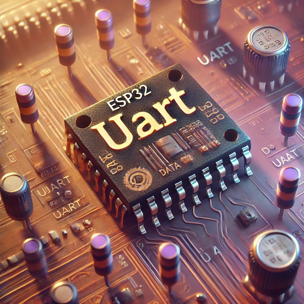
UART is a hardware-based protocol used for serial communication between microcontrollers and other devices. It uses two wires: TX (transmit) and RX (receive). Data is transmitted one bit at a time on these two lines, and UART communication is asynchronous, meaning it doesn’t require a shared clock signal to control data transmission.
UART
UART communication uses two main lines:
- TX (Transmit): Sends data to another device.
- RX (Receive): Receives data from another device.
UART communication is asynchronous, meaning there is no need for a shared clock. Instead, both devices agree on a baud rate (the number of bits transmitted per second) to ensure proper data transfer.
ESP32 UART Hardware Features
We’ll use the UART port on the ESP32 for serial communication. Here’s the basic wiring setup:
- TX Pin: Connect the ESP32 TX pin to the RX pin of the receiving device.
- RX Pin: Connect the ESP32 RX pin to the TX pin of the sending device.
- GND Pin: Connect the ESP32 GND pin to the GND of the external device.
Wiring Diagram:
ESP32 (TX) ----> External Device (RX)
ESP32 (RX) <---- External Device (TX)
GND -------------------- GND
Using the ESP32-PICO-KIT
Hardware Background:
- GPIO16 and GPIO17 are the default pins for UART0 on the ESP32 module, which are connected to the USB-to-UART interface for programming and serial monitoring.
- These pins are used internally and cannot be used for external UART communication.
Alternative Method:
- Use GPIO21 (TX) and GPIO22 (RX) as the UART2 transmission and reception pins.
- GPIO21 and GPIO22 are general-purpose pins that can be used for UART or other peripheral communications, and are freely available on the ESP32-PICO-KIT.
Code for ESP32 UART
To initialize UART on the ESP32, we need to set up the baud rate, data bits, stop bits, and other parameters. The ESP32 supports up to three UART ports, each of which can be configured with different settings.
#include <stdio.h>
#include <string.h>
#include "freertos/FreeRTOS.h"
#include "freertos/task.h"
#include "driver/uart.h"
#include "driver/gpio.h"
#include "esp_log.h"

static const char *TAG = "uart_test";

// UART configuration
#define UART_NUM UART_NUM_2        // Using UART2
#define UART_TX_PIN GPIO_NUM_21    // TX Pin
#define UART_RX_PIN GPIO_NUM_22    // RX Pin
#define UART_BAUD_RATE 115200      // Baud rate
#define BUF_SIZE 256               // Buffer size

// UART initialization function
static void uart_init() {
    // Check if UART driver is already installed, and remove it if necessary
    if (uart_is_driver_installed(UART_NUM)) {
        uart_driver_delete(UART_NUM);
        vTaskDelay(pdMS_TO_TICKS(100));  // Allow time for proper cleanup
    }

    // UART configuration structure
    uart_config_t uart_config = {
        .baud_rate = UART_BAUD_RATE,
        .data_bits = UART_DATA_8_BITS,
        .parity = UART_PARITY_DISABLE,
        .stop_bits = UART_STOP_BITS_1,
        .flow_ctrl = UART_HW_FLOWCTRL_DISABLE,
        .rx_flow_ctrl_thresh = 122,
        .source_clk = UART_SCLK_APB,
    };

    // Configure UART parameters
    esp_err_t err = uart_param_config(UART_NUM, &uart_config);
    if (err != ESP_OK) {
        ESP_LOGE(TAG, "UART parameter config failed with error: %d", err);
        return;
    }

    // Set UART pins
    err = uart_set_pin(UART_NUM, UART_TX_PIN, UART_RX_PIN, UART_PIN_NO_CHANGE, UART_PIN_NO_CHANGE);
    if (err != ESP_OK) {
        ESP_LOGE(TAG, "UART set pin failed with error: %d", err);
        return;
    }

    // Install UART driver
    err = uart_driver_install(UART_NUM, BUF_SIZE, BUF_SIZE, 0, NULL, 0);
    if (err != ESP_OK) {
        ESP_LOGE(TAG, "UART driver install failed with error: %d", err);
        return;
    }

    ESP_LOGI(TAG, "UART initialized successfully");
}

// UART transmission task
void uart_tx_task(void *arg) {
    const char* test_str = "Hi UART\n";
    while(1) {
        // Send test string
        if(uart_write_bytes(UART_NUM, test_str, strlen(test_str)) > 0) {
            ESP_LOGI(TAG, "Sent: %s", test_str);
        } else {
            ESP_LOGE(TAG, "Failed to send data");
        }
        vTaskDelay(pdMS_TO_TICKS(2000));  // Send data every 2 seconds
    }
}

// UART reception task
void uart_rx_task(void *arg) {
    uint8_t data[BUF_SIZE];  // Buffer to store received data
    const char* welcome_msg = "Hello, welcome!\n";

    while(1) {
        // Read data from UART
        int len = uart_read_bytes(UART_NUM, data, sizeof(data) - 1, pdMS_TO_TICKS(100));
        if(len > 0) {
            data[len] = '\0';  // Null-terminate the received string
            ESP_LOGI(TAG, "Received %d bytes: %s", len, data);

            // Check if received string matches "Hi UART"
            if (strncmp((char*)data, "Hi UART", 7) == 0) {
                uart_write_bytes(UART_NUM, welcome_msg, strlen(welcome_msg));  // Send welcome message
                ESP_LOGI(TAG, "Sent welcome message");
            }
        }
        vTaskDelay(pdMS_TO_TICKS(50));  // Add delay to avoid task overload
    }
}

void app_main(void)
{
    // Wait for the system to stabilize
    vTaskDelay(pdMS_TO_TICKS(1000));

    // Initialize UART
    uart_init();

    // Allow additional time for initialization to complete
    vTaskDelay(pdMS_TO_TICKS(100));

    // Create tasks for sending and receiving
    xTaskCreate(uart_tx_task, "uart_tx_task", 2048, NULL, 5, NULL);
    xTaskCreate(uart_rx_task, "uart_rx_task", 2048, NULL, 5, NULL);

    ESP_LOGI(TAG, "UART tasks created");
}
Code Explanation
The code configures the ESP32-PICO-KIT V4 to use UART2, with GPIO21 as the TX pin and GPIO22 as the RX pin. It implements a simple communication system with the following tasks:
- ESP32 UART Initialization: The
uart_initfunction configures the UART parameters, such as baud rate, data bits, stop bits, and flow control. It also sets the TX and RX pins (GPIO21 and GPIO22) and installs the UART driver. - ESP32 UART Transmission Task (uart_tx_task): This task sends the string “Hi UART” every 2 seconds. If the transmission is successful, it logs the sent message; if it fails, it logs an error.
- ESP32 UART Reception Task (uart_rx_task): This task continuously listens for incoming data on UART2. If the received message is “Hi UART”, it responds with the string “Hello, welcome!”.
Output Explanation
ESP32 UART Initialization:
After successfully initializing the UART, the system logs the configuration of the TX pin (GPIO21) and RX pin (GPIO22). If there is any error during configuration, it will log the corresponding error message.
ESP32 UART Transmission Task (uart_tx_task):
The transmission task sends the string “Hi UART” every 2 seconds. If successful, it logs the following:
I (698413) uart_test: Sent: Hi UARTESP32 UART Reception Task (uart_rx_task):
The reception task listens for incoming data. When it receives “Hi UART”, it sends back “Hello, welcome!” and logs:
I (722413) uart_test: Received 7 bytes: Hi UART
I (726413) uart_test: Sent welcome message
Conclusion
Mastering UART communication on the ESP32 opens up numerous possibilities for your projects. By understanding the basics and implementing the examples in this guide, you can integrate reliable and efficient serial communication into your designs. Whether for simple data transfer or more complex applications, UART is a versatile and valuable tool in the embedded systems world.
The ESP32 provides robust hardware support with multiple UART ports, making it an ideal choice for projects requiring serial communication. We hope this guide helps you get started quickly and successfully implement UART functionality in your next ESP32 project!
